
Imagine trying to turn a piece of metal into a car component but in the end, the component fails to fit into your car.
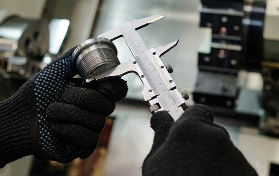
Machining any component necessitates carelessness and accuracy. However, miscalculations may occur leading to inaccurate dimensions.
These parameters, often expressed in numbers allow you to craft befitting and functional products and components.
What is Engineering Tolerance?
Engineering tolerance is a discrepancy in one or several features of your manufactured product. This allowed flow in dimension reminds you that every product manufactured with the help of human hands is subject to an error margin.
You must think about these margins of error during manufacturing to ensure that your products meet or exceed any set quality standard.
What is the Difference between Engineering Tolerance and Allowance
In engineering, allowance is a heavily used term and it relates to the surplus material factored in during manufacturing.
This extra material ensures that your final product meets your dimensional standards. Engineering tolerance, on the other hand, explains acceptable dimensional flows.
| Features | Engineering Tolerance | Engineering Allowance |
| Purpose | Make certain that your components function properly and fit perfectly. | Accounts for engineering tolerances. |
| Relationship | Takes into consideration allowed engineering allowances. | It determines the engineering tolerances you must factor in. |
| Examples | A fastener such as a bolt with a dimension tolerance of + 0.05 mm. | A hole meant to house a bolt but is 0.05 mm bigger. |
Types of Engineering Tolerances
Even the most perfect components or products exhibit some degree of tolerances. These tolerances ensure that your components fit perfectly and function as required. Here are the distinct types and the reasons why they matter.
Dimension Tolerance
Dimension tolerance is the permissible discrepancy in the measurement of your component. Think of it as the wiggle room engineers and manufacturers observe when producing machinable parts.
It is simply the difference in a component’s actual size compared to the intended size. This difference however does not impact your component’s functionality.
Terms that Define Dimension Tolerance
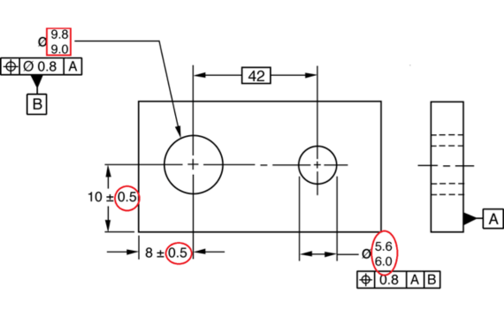
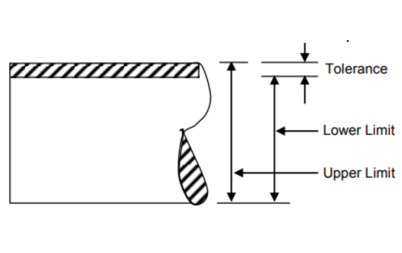
- Nominal Size: The nominal size or value is the measurement you have in mind when manufacturing your component or product. It is the size you intend to achieve and it does not factor in any engineering tolerance. It is simply your middle ground.
- Lower Deviation: This is the lower limit of your component’s physical size. It tells you how much smaller your component can be without impacting its functionality or performance. Besides, it is a figure that is slightly lower than your nominal size.
- Upper Deviation: This is the upper limit and it connotes how much bigger your component can be while maintaining its functionality. This is often a figure that is slightly bigger than your nominal size. For instance, a shaft measuring 50 mm is likely to have an upper deviation of +0.1 mm.
- Tolerance Zone: This is often indicated as a range and it includes the upper and lower deviation. It simply tells you how big or small your component can be without impacting its functionality. For instance, ±0.1 mm, which shows the accepted upper and lower variations.
· Unilateral Tolerance
Unilateral tolerance is a unique type of dimension tolerance and it factors in an upward or downward flaw in the size of your manufactured component. It looks at the variation in length, diameter, or width of your component.
However, this variation in physical size can only be in one direction. For instance, a screw whose intended size is 20 mm but has a unilateral tolerance of + 0.2 mm. This means that even a screw measuring 20.2 mm will fit into your respective hole.
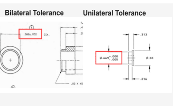
· Bilateral Tolerance
This tolerance addresses distinction in the physical of your component’s bot upwards and downwards. Bilateral tolerance indicates the acceptable flow in diameter, length, or width of your components.
This range can be positive or negative. A good example of bilateral tolerance is a screw or bolt hole whose intended diameter is 50 mm but with a tolerance of ±0.2 mm. This means that you can fit a screw or bolt measuring 49.4 mm and 50.2 mm.
· Limit Tolerance
This tolerance is often indicated as two distinct values and it factors in the lowest and highest dimensional flaws that will not affect the functionality of your component.
A good example of limit tolerance is a shaft that comes marked as 20 mm and 20.5 mm. 20 mm refers to the acceptable minimum size while 20.5 mm refers to the acceptable maximum size.
· Symmetrical Tolerance
Symmetrical tolerance factors dimensional variations below and above your intended measurements. This variation is evenly distributed and it means that your component may be bigger or smaller than your nominal size.
For instance, when manufacturing bolts whose intended diameter is 30 mm, you may factor in a symmetrical tolerance of ±0.1 mm. This means that even bolts with a diameter of 29.9 mm or 30.1 mm are acceptable.
· Asymmetrical Tolerance
This tolerance allows you to deviate your component’s size unequally above or below the nominal size. This allows you to manufacture parts and components that fit perfectly. Asymmetrical tolerance is evidenced in screw holes.
For instance, a hole with a diameter of 40 mm and asymmetrical tolerance of +0.2 mm/-0.1 mm means that this hole can accommodate screws measuring 39.9 mm and 40.2 mm.
Geometric Tolerance
Geometric tolerance is a permissible discrepancy in the shape or form of your manufactured component. This acceptable flow in orientation is quite insignificant and it hardly impacts the functionality of your component.
These variations are often indicated using symbols, which are defined in the ISO 1101 and ASME Y14.5 standards. They include;
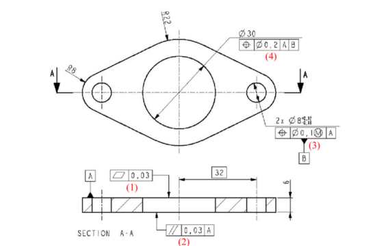
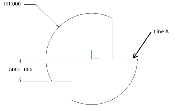
· Form Tolerance
Form tolerance factors in acceptable flaws regarding the shape of your component. Components with form tolerance do not feature your intended shape but this does not mean that their functionality deteriorates. These variations are further divided into;
- Cylindricity: This form of tolerance focuses on cylindrical components and it accounts for the flaws in your component’s cylindricity. It looks at the straightness along your component’s length and its circularity.
- Straightness: This type of form tolerance focuses on the straightness of your component’s edges and axes. It makes certain that your component fits well and works perfectly despite the variation in shape. However, it must be within a certain range for it to be acceptable.
- Circularity: This form tolerance is specifically related to cylindrical components only and it ensures that your component has a uniformly spherical orientation. For instance, a hole meant to hold screws must have a radius whose circularity variation is within a certain range.
- Flatness: This type of form tolerance factors in variations in the flatness of your machined component. A good example of flatness variation is a baseplate which must demonstrate flatness for it to settle on other components.
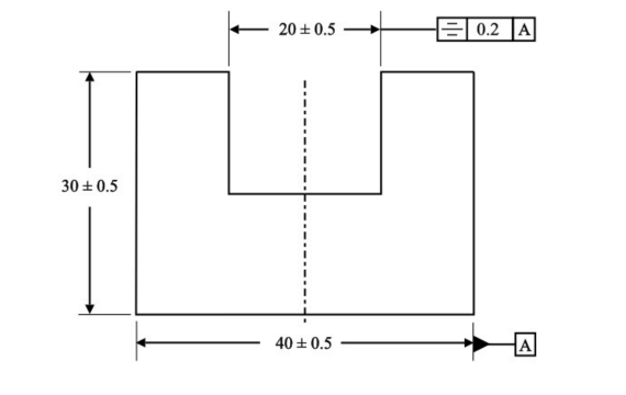
· Location Tolerance
This type of engineering tolerance specifies the allowable discrepancy in the positioning of your components, which form a system. Location tolerances are further divided into;
- Symmetry: This specifies the permissible flaw in the symmetrical relationship of your manufactured component. A good example of symmetry variation is the positioning of a slot within your system.
- Position: This type of location tolerance looks into the acceptable variation of your component’s positioning within a system. For instance, the positioning of the screw holes on your component.
- Concentricity: This specifies the positioning of your adjacent components. This variation makes certain that the positioning of these features is within a permissible tolerance range thus guaranteeing optimal performance.
· Orientation Tolerance
This tolerance focuses on the angling of your component thus impacting how it bonds with other components. Orientation tolerances, unlike other types of geometric tolerances, specify the permissible variation in your component’s angling. They are divided into;
- Angularity: This type of orientation tolerance addresses the variation in the angling of your component in relation to other components. For example, a shaft that sits at 90 degrees of your base plate.
- Parallelism: This tolerance accounts for the variation in the parallelism of your respective component. It ensures that your machined part sits parallel to your plane or other component.
- Perpendicularity: Unlike the other types of orientation tolerances, this tolerance addresses the acceptable fluctuation in the perpendicularity of your component. Does it sit perpendicular to your specified line?
· Runout Tolerance
This type of geometric tolerance seeks to address permissible fluctuation in the distance between your rotating component and your datum axis.
This variation is essential especially when you are dealing with rotating components such as spindles and shafts. It is divided into;
- Total Runout Tolerance: This gives you a specific tolerance range regarding the cylindricity and circularity of your rotating component. Total runout tolerance makes certain that your component runs perfectly and serves its intended purpose.
- Circular Runout Tolerance: Circular runout tolerance addresses the variation in the concentricity and circularity of your rotating components. Observing the circular runout tolerance range guarantees proper functioning.
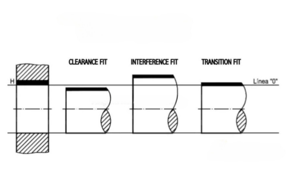
Fit Types
Fit is a heavily utilized engineering term and it refers to how your distinct components interact and work harmoniously to contribute to the proper functioning of your system. Fits give you a glimpse of how your components will work once you assemble them. They come in varying forms including:
· Interference Fit
This type of fit sees your respective components overlap as they link. It creates a very tight connection meaning that your components are securely held.
A good example of an interference fit is a shaft that is manufactured relatively bigger than the hole it is intended to fit into. This eliminates any wiggle room while improving your load transmission.
· Clearance Fit
This type of fit requires you to deliberately leave a gap or space alienating your distinct components. Clearance fits make it easier for your components to rotate or move.
They also make it easier for you to assemble these components, access them for maintenance, and even disassemble them. Clearance fits are often utilized in gears and bearings.
· Transition Fit
This type of fit thrives in scenarios where you want to ease the process of assembling your components. It also works well in instances where your primary priority is to achieve alignment accuracy.
It results in both clearance and interference meaning that the interaction between your mating components can be loose or tight. Transition tits reign supreme in some distinct types of couplings.
Picking the Perfect Engineering Tolerance
Failing to observe engineering tolerance ranges can lead you into a scenario where you are trying to fit a square peg into a spherical hole.
Getting your dimensions right not only guarantees a perfect fit but it directly impacts the performance of your component. This explains the need for getting your engineering tolerances right and you can accomplish this by:
- Understanding Your Requirements: To begin with, get to know the exact requirements of your application or project. What function do you expect your component to serve and what operating conditions will you be working with? This will help you settle on the right dimensions.
- Assess Your Manufacturing Process and Equipment: Look at your manufacturing capability. Do you have the capacity to produce high-quality components with the right dimensions and tolerances? Understand what you need to manufacture your components.
- Observe Industry Standards: Have industry standards and guidelines as your reference point. Consult ISO standards regulating your specific component. Also, look into ASME Y14.5 since it stipulates the respective tolerances for most machined components.
- Get in Touch With an Expert: Do not shy away from asking for advice or direction from renowned and certified professionals. Talk to quality control technicians as well as engineers before picking your ideal engineering tolerance.
When manufacturing or machining any component, especially metal components like shafts and gears, you cannot afford to disregard dimensional accuracy.
Factoring in tolerances ensures that your constituent fits perfectly into your system and functions excellently. Engineering tolerances simply ensure that your component fits perfectly just like a puzzle piece.
More resources:
Large Part Machining – Source: KDM
Tolerance in Engineering – Source: WIKIPEDIA