

Engineered products such as engines, transmissions, CNC machines, conveyor systems, and more are composed of different components that slip or fit each other. Therefore, they operate properly and perform their primary function. However, engineered products, on deeper thoughts come with complex processes before they get to perform their application. It includes understanding the term in mechanical engineering called “fit” and its different types.
In this article, we will discuss what is fit, its different types, its applications, and related terms that will be helpful in fully understanding the topic. This article will also help you find the right fit for your project. Keep reading!
What is Fit?
In engineering, the term fit refers to the relationship between two mating parts of components in order to deliver their specific function.
It also refers to how these components are intended to fit together when it comes to their clearances, tolerances, and dimensions.
Engineering fit determines the component’s level of looseness or tightness in their connection.
Importance of Understanding Fit
Engineering fit is crucial in manufacturing and designing processes since they determine the mating component’s clearance based on size requirements.
Choosing the right fit allows easy rotation of the shaft through the hole. Therefore, fit is necessary to ensure that parts are assembled correctly and function as intended.
Fits and Tolerances
When it comes to identifying the component’s assembly, fits and tolerances are the most common elements that go together. Hence, understanding these two terms can be a factor in creating a successful component assembly.
Tolerance refers to the distance between the minimum and maximum size. It is commonly characterized by a positive value and a number that doesn’t have a sign.

Tolerance Grades
Tolerance grades are used to indicate the level of accuracy in every component or part. Overall, there are a total of 18 tolerance grades used in engineering. It includes the following:
IT01, IT0, IT1, IT2, IT3, and IT4: These tolerance grades are used for producing measuring instruments, plug gauges, gauges, and more.
IT5, IT6, and IT7: Commonly used for fits in precision engineering requirements.
IT8, IT9, IT10, IT11: These tolerance grades are used for general engineering.
IT12, IT13, IT14: Typically utilized tolerance grades for press or sheet metal working.
IT15 and IT16: Used for different processing including general cutting and casting work.
The Basis of Fit: Hole and Shaft System

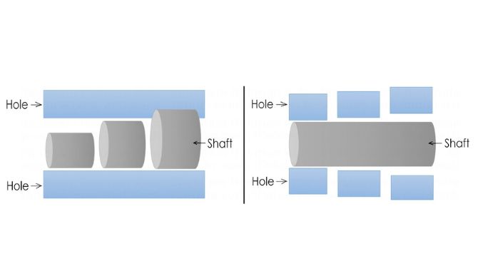
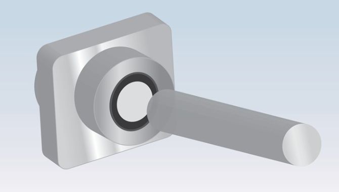
The hole and shaft system serves as the basis for defining engineering fits. It plays a crucial role in ensuring that components fit together properly. This system involves the relation between the hole and the shaft.
In the hole basis system, the hole size is kept constant and the shaft diameter is varied to give the various types of fits. In this system, the lower deviation of the hole is zero. The hole’s upper limit and shafts’ two limits are then varied to give the desired type of fit.
Meanwhile, for the shaft basis system, the shaft size is kept constant and the size of the hole is varied to achieve the desired fit. The upper deviation of the shaft is zero.
Why Hole Basis System is Widely Used than Shaft Basis System

The holes are commonly done through different methods such as broaching, reaming, boring, drilling, and more. While the shafts are typically done by grinding or turning.
When you use a shaft system as a basis to obtain the type of fit or specify a unit of dimension, it will require different holes with various sizes. This will also require lots of tools which will increase the production cost.
Whereas, using the hole system as the basis to obtain fit, will only require one tool to create the hole. This will also allow the shaft to be machined easily into different sizes. Hence, reducing the production cost. That is why the hole basis system is widely used compared to the shaft basis system.
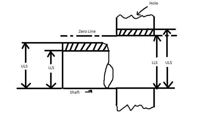
Hole and Shaft: Their Minimum and Maximum Limit


Both holes and shafts have their maximum and minimum limit. The minimum and maximum limits of holes and shafts are defined within a range called the tolerance.
The minimum limit refers to the minimum diameter or actual size of the shaft. On the other hand, the maximum limit also refers to the largest allowable diameter or dimension of the shaft.
Additionally, the hole’s minimum limit is the smallest allowable diameter or dimension. While the maximum limit is the largest allowable diameter or dimension of the hole.
It is important to note that the minimum limit is not smaller or the maximum limit does not exceed the size needed for its intended function.
How Do We Name Different Types of Fit Used in Engineering?
Knowing how fits are named is important for choosing the right fit for your product.
The International Organization for Standardization states that a particular fit is named using an alpha-numeric code that also indicates its tolerance. The alphabet part indicates the code for the shaft or hole. The code for the hole is indicated by an upper-case letter while the shaft is indicated by a lower-case letter. Take this code as an example: H7/h6
*H7 is the hole’s tolerance range
*h6 is the shaft’s tolerance range
This coding enables engineers and designers to distinguish the hole and shaft’s upper or lower size.
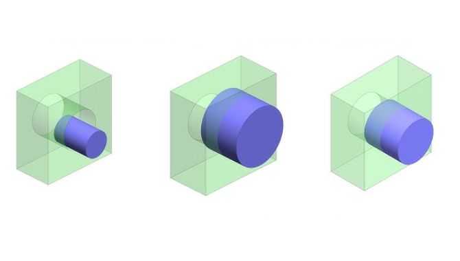
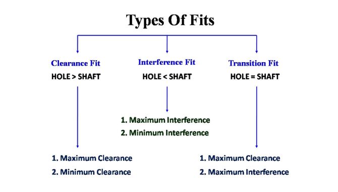
Different Types of Fit
- Clearance Fit
- Interference Fit
- Transition Fit
Clearance fit refers to the components that have free movement or loose mating. Therefore, this fit is used for designing a product requiring components that can be easily slid in and out.
In this type of fit, the shaft is smaller compared to the hole. Therefore, the shaft can slide and rotate inside the hole swiftly.

Clearance fit is also sub-categorized into 6 fits according to how loose they are. It includes the following:
Sliding Fit
The shaft and the hole have almost zero clearance but provide more precision and accuracy. Thus, parts with sliding fit can slide in and rotate freely.
Example of components with sliding fit:
- Sliding Gears
- Automobile Assemblies
- Slide Valves
- Clutch Discs
- Guiding of Shafts
- Tailstock Spindle
- Machine Tool Parts, and more.
Location Clearance Fit
Location clearance fit has also minimal clearance for applications that require high-accuracy and precision. Parts with locational clearance fit can be lubricated so it can turn and slide easily without exerting any force.
Example of components with location clearance fit:
- Guiding of shafts
- Roller guides
Running Fit
Running fit usually has a large clearance where the shaft can rotate inside the hole at a moderate speed. It also involves heavy journal pressure and large temperature variations. Thus, making it suitable for applications where accuracy is not the primary requirement.
Example of components with running fit:
- Gears
- Couplings
Close Running Fit
Close running fits are applicable for applications that needs only a small clearance when it comes to accuracy.
Loose Running Fit
Loose running fit has the largest clearance among the types of clearance fits. Due to that, parts can rotate at a higher speed. This makes it suitable for application where accuracy is not necessary.
Example of component with loose running fit:
- Latches
- Pivots
- Heat
- Parts that are affected by contamination and corrosion
Free Running Fit
When the shaft and hole have a small clearance, it is called a free running fit. It is used for components with slow regular or non-regular motions requiring little accuracy.
Example of components with free running fit:
- Piston
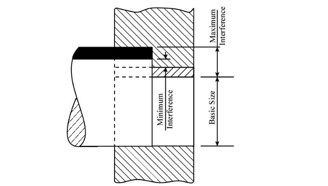
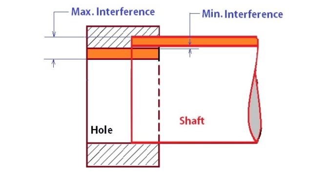
Interference fit is also known as friction fit or press fit which is tighter compared to clearance fit. Generally, in interference fit, the hole’s size is smaller than the shaft’s size.
Therefore, making a fit between two components requires high force to push them together. Assembling and disassembling components with interference fit uses different methods such as hammer or hydraulic press.
You can also heat the hole, put the shaft in it, then let it become cool. Once cooled, the hole and shaft will shrink together, making an interference fit.
Interference fit has three different kinds including:
Press Fit or Tight Fit
Assembling component with press fit is done through cold pressing. Therefore, it only requires minimal interference.
Example of component with press fit:
- Conveyor’s stepped pulley
- Machine’s cylindrical grinding
Driving Fit
Driving fit requires more interference compared to press fit, making it more reliable. Components can be assembled using hot or cold forging to ensure higher force.
Example of components with driving fit:
- Shafts
- Gears
- Bushes
Force Fit
With force fit, mating two components requires higher interference and external force. The hole will be heated using a very high temperature to insert the shaft.
Example of component with force fit:
- Gears
- Shafts
Transition fit or slip/push fit lies in between clearance and interference fit. Thus, making it a suitable choice for applications where accuracy is the primary requirement. Compared to interference fit, transition fit tends to have more clearance yet not enough to provide joint movement.
In this fit, the shaft is thicker than the hole. Therefore, components with transition fit can be fitted to each other using minimal pressure only.
This fit is a perfect choice when aligning the mating component that requires higher precision.

Transition fit has also two categories including:
Similar Fit
This has very small clearance and interference. Thus, assembly can done by using a rubber mallet.
Example of components with similar fit:
- Gears
- Hubs
- Pulleys
- Bearing
- Dowel pin
- Ring gauge
Fixed Fit
This fit has a very small clearance and only requires less interference. Components can assemble and disassembled through light force.
Example of components with fixed fit:
- Driven bushes
- Armatures
- Plugs
Achieving Dimensional Tolerances for Fits
Tolerance is a crucial factor in ensuring a precise and accurate fit. However, it is a very skillful and complex task to produce the mating parts within the necessary tolerance.
The GD&T sets a tolerance limit that is acceptable from the actual geometry. Hence, manufacturers and fabricators should produce the components adhering to the said limit.

To achieve the limit, manufacturers can use several methods including:
CNC Machining
CNC precision machines can provide up to +/-0.001mm accuracy. Therefore, manufacturers can fabricate components with high accuracy using appropriate fixtures and tools.
Grinding
Grinding is an ideal solution for machinists who want to produce components with ultra-precision. Due to its +/-0.25 microns accuracy, grinding is widely used for applications with interference fit.
Reaming
Reaming is widely used for the hole-making process. This can remove very tiny material, it can surely provide holes that are within the range of required tolerance for every fit.
Choosing the Right Engineering Fit for Your Project
Below are the different factors that you should consider before choosing a fit for your project.
Application
Each engineering fit has its specific function and purpose. Thus, you can decide which fit you choose based on your requirements. You may consider your project’s function, tolerance, and accuracy before choosing a fit.
Budget
Engineering fits that have tighter tolerances are more likely to be expensive. Therefore, before deciding, you should also consider your budget range. We recommend that you choose a fit that will provide you with the right dimensional tolerance required by your project to function.
Tolerance
Do you want your part to rotate in full circle or tight? Answering this question can help you decide which fit you will choose. Additionally, learning the concept of tolerance and being specific with your request can also help in choosing the right fit for your project.
Conclusion
As discussed in this article, there are various factors that are related to understanding the different types of fits. Clearly, learning about fits, how it works, and its applications will guide you to producing the accurate components. Applying your learnings in this article, will also help you choose the right fit for your application.
If you want to learn more about the best solution for your project, we at KDM will gladly assist you.